Thermal bridging
Thermal bridging modelling of linear junctions to determine heat loss and internal temperature.
- Linear Thermal Transmittance (w/mk) Ψ-Value (psi)
- Point thermal bridging (w/K)
- Temperature Factor (Surface condensation) (fRsi).
In earlier versions or Approved Document Part L, prior to 2021 changes it was acceptable to use generic values for linear thermal loss from illustration drawings which are commonly known as Accredited Construction Details (ACD).
Accredited Construction Details (ACD) are no longer acceptable for use in compliance calculations, SAP / HEM for the purpose of Part L compliance so it would be a case of using thermally modelled psi values from modelled architectural details or default values.
There is a wide range of off the shelf details from schemes such as the Recognised Construction Details and Structural Timber Frame Association which provide calculated models which are based on specific architectural details.
Thermal bridging junctions which are different to the proposed construction details can be modelled to determine both Linear Thermal Transmittance and Temperature Factor.
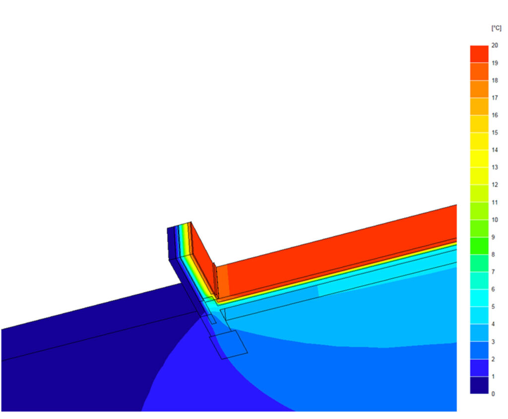
Example 3D model showing temperature distribution of a (E5) ground floor/wall junction.

Copyright 2026 - Eco-Survey - Anderson-Goddard Ltd - VAT No 644 035165 : 4789524 Registered in England and Wales
Contact Donna Goddard on Tel. 01925 733942
Email at info @ eco-survey.com
Abacus House, 450 Warrington Road Culcheth Cheshire WA3 5QX
website by stepholt
Contact Donna Goddard on Tel. 01925 733942
Email at info @ eco-survey.com
Abacus House, 450 Warrington Road Culcheth Cheshire WA3 5QX
website by stepholt